This is the second post in a series about making PCB art. You can read the first one here.
In the past post, I covered what PCB art is, the general PCB design process, and some important ideas to keep in mind. Notably, we want to find and fix problems before we start using circuit design tools, and especially before we start manufacturing things.
Here are the steps again:
- Ideation
- Prototyping/breadboarding ← you are here
- KiCad schematic + board layout
- First “board spin”: order a set of PCBs, assemble them, test them
- Fix any issues
- Another board spin if needed
- Fix any issues, repeat until you have a final product or you run out of time.
In this phase, we want to buy components that allow us to test out our design on a breadboard.
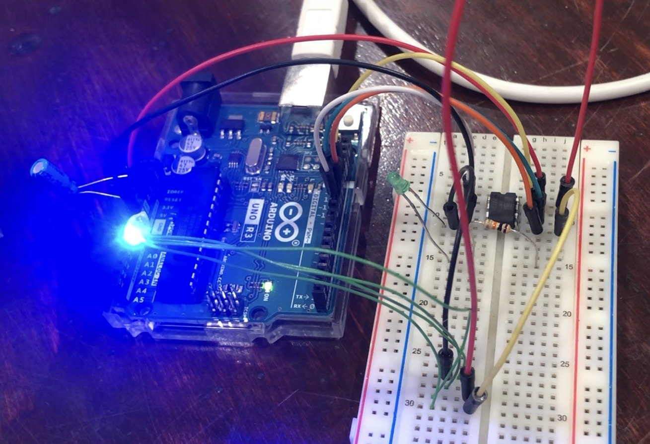
We’ll start with core functions. In the case of this simple, artistic design, that just means LEDs being driven by a microcontroller. Then we’ll slowly evolve our circuit until it’s as “badge-like” as possible.
That means we start powering it off a bench top power supply, but then move it to a battery (with associated circuitry), and other similar modifications.
In a more practical engineering design (a circuit that primarily has a technical purpose), this process would be iterative in a way that focuses on technical constraints and business concerns such as cost, timeline, etc.
But we also have an artistic aspect to our project. This means that our process is iterative in a technical and artistic way, where our technical choices influence the ✨ aesthetic ✨ and vice versa.
If you are new to PCB design, and especially if you’re new to artistic PCBs, I would recommend allotting extra time to get the art figured out. As you’ll see in this blog post, the artistic and technical constraints play off of each other.
Here’s the three main problems we’ll discuss in this blog post:
- LED selection and brightness
- Artwork
- How this will be powered
LED selection
In the first post I talked about backlit PCBs, where the LED light is shining from the back of the board, through exposed FR4, to the front of the board.
This is done with either reverse mount or side-view LEDs.
- A normal LED would sit on the surface of the board, and the light would shine up and away from the board (orthogonal).
- A reverse mount LED is a very similar package, but has pads (feet) that allow the LED to point downward. This requires the soldermask to be removed so that the light can shine through the board, as the LED will be placed on the back side of the PCB.
- Last but not least is a side-view LED package, where the light is shining (mostly) parallel to the board.
Here’s what the PCB layers look like, roughly speaking:
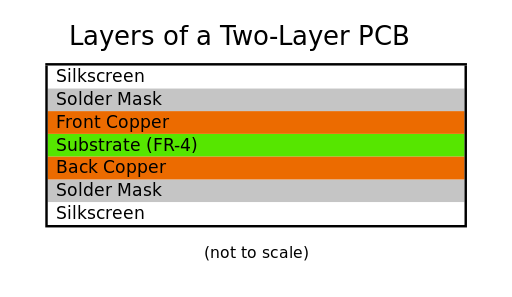
FR4 is the core of the board, with copper on either side to make the traces (electrical connections), solder mask on top of that to protect the copper traces, and then silkscreen on top to label components. This is assuming a 2-layer board.
Here’s a drawing of what I originally envisioned in terms of art and PCB layers:
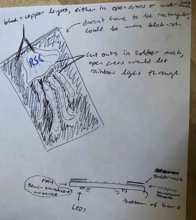
Normally speaking, the FR4 is going to be 1.6mm thick, but we can request other thicknesses too.
Sideview and reverse mount aren’t the only options here. You can also have two PCBs stacked on top of each other. The bottom board has ‘normal’ LEDs, and the second board has solder mask removed in a specific pattern. Here’s an example:
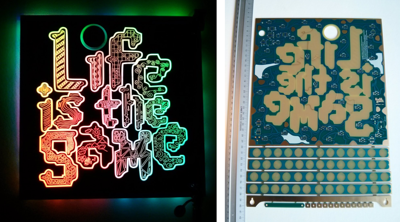
It looks really good! But I didn’t want to go this route because of the added weight (for a wearable badge), and because I wanted to try sideview LEDs.
Another option would be front-facing LEDs with custom-etched acrylic as the top layer. I’d like to try this in the future but unfortunately the timing didn’t work out this time.
Instead, I decided on a single board with exposed FR4, sideview LEDs on the back. So, as any normal person does, I found some FR4 in my electronics stockpile and tested it with some side-view LEDs I bought from Digikey. I bought LEDs in green, yellow, red, and blue.
The photos below make the LEDs appear very bright, but unfortunately this is just my phone’s color/light balancing settings.
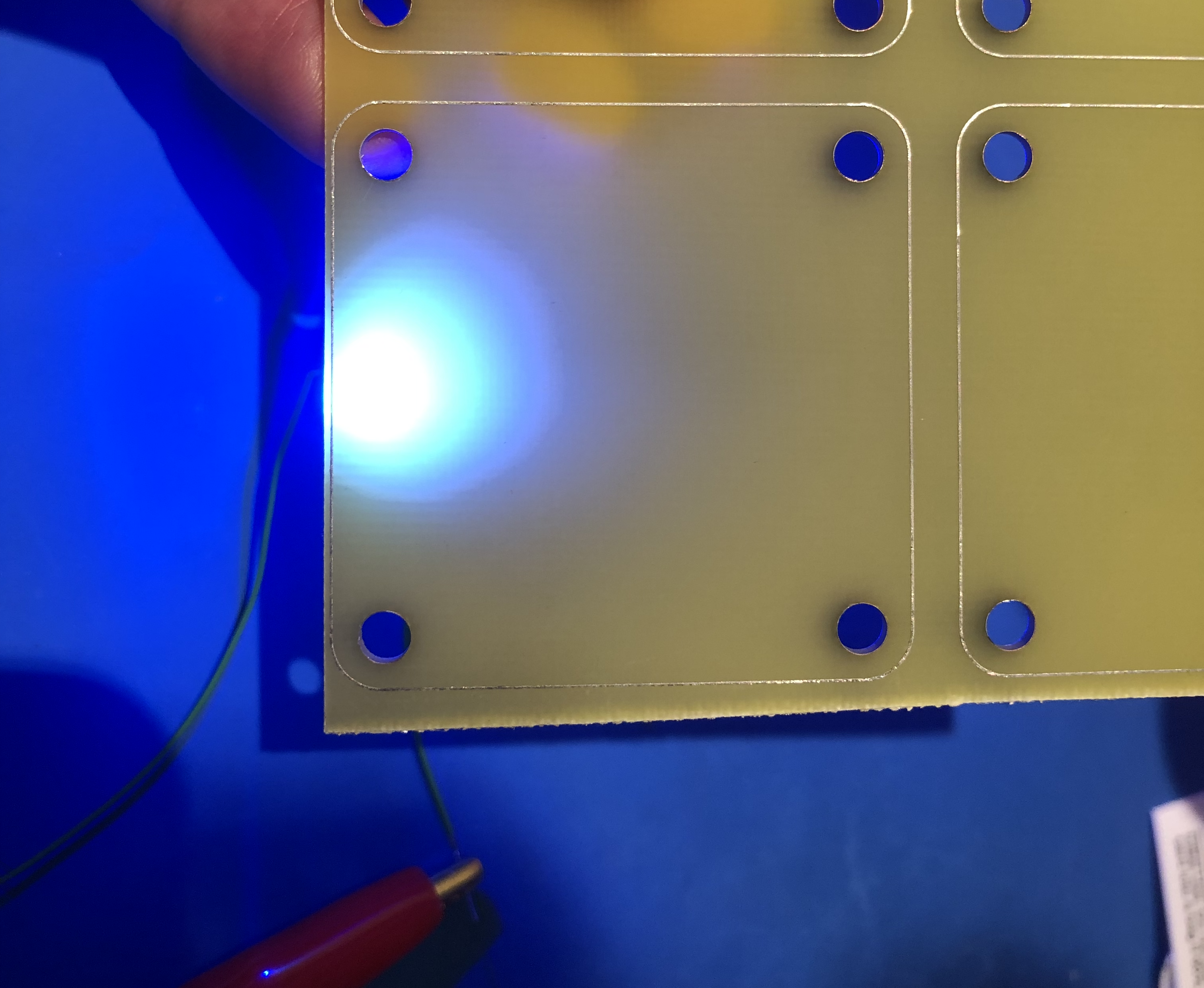
The takeaway here is that the first LEDs I tested with were not bright enough. At least not bright enough for me!
We can order PCBs that are thinner than 1.6mm, meaning that there’s less FR4 for the LEDs to shine through, and the LEDs appear brighter. But brightness isn’t the only issue here.
LEDs impose a lot of constraints in our design.
The more LEDs we have, the faster our battery drains…
…and more LEDs = more BOM (bill of material cost)…
… but we need enough LEDs to cover all of the jellyfish art area!
Additionally, we have art limitations with respect to the LEDs too. I wanted to do a rainbow gradient similar to this Daft Punk helmet SAO, which would require a mix of LED colors.
Different colored LEDs have different forward voltages, which complicates our design. The forward voltage is the voltage level below which the LED will not light.
Even worse, did you know that the human eye perceives different colors to have different brightnesses?
I learned quite a bit about measures and perception of brightness during this portion of the project. I also found this handy tool that lets you convert from wavelength (as you would see on a Digikey or Mouser part listing) into a HEX code to help approximate the design.
Art
Our goal for this section is to get from an idea all the way to a final art sketch that looks good and also fits our technical constraints.
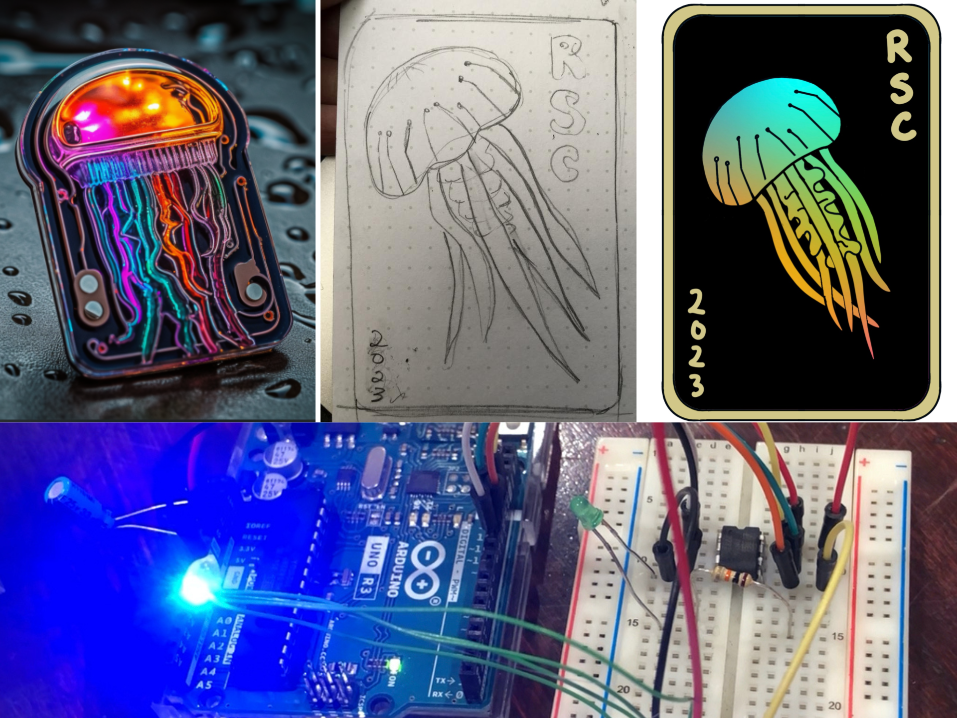
We had an artist, Corvulu, volunteer to help us with the design. We also used some AI tools to generate ideas, as shown below. We weren’t necessarily tied to the idea of having a realistic jellyfish. We wanted something that looked cool, and that would work as a badge (able to be powered with batteries, etc).
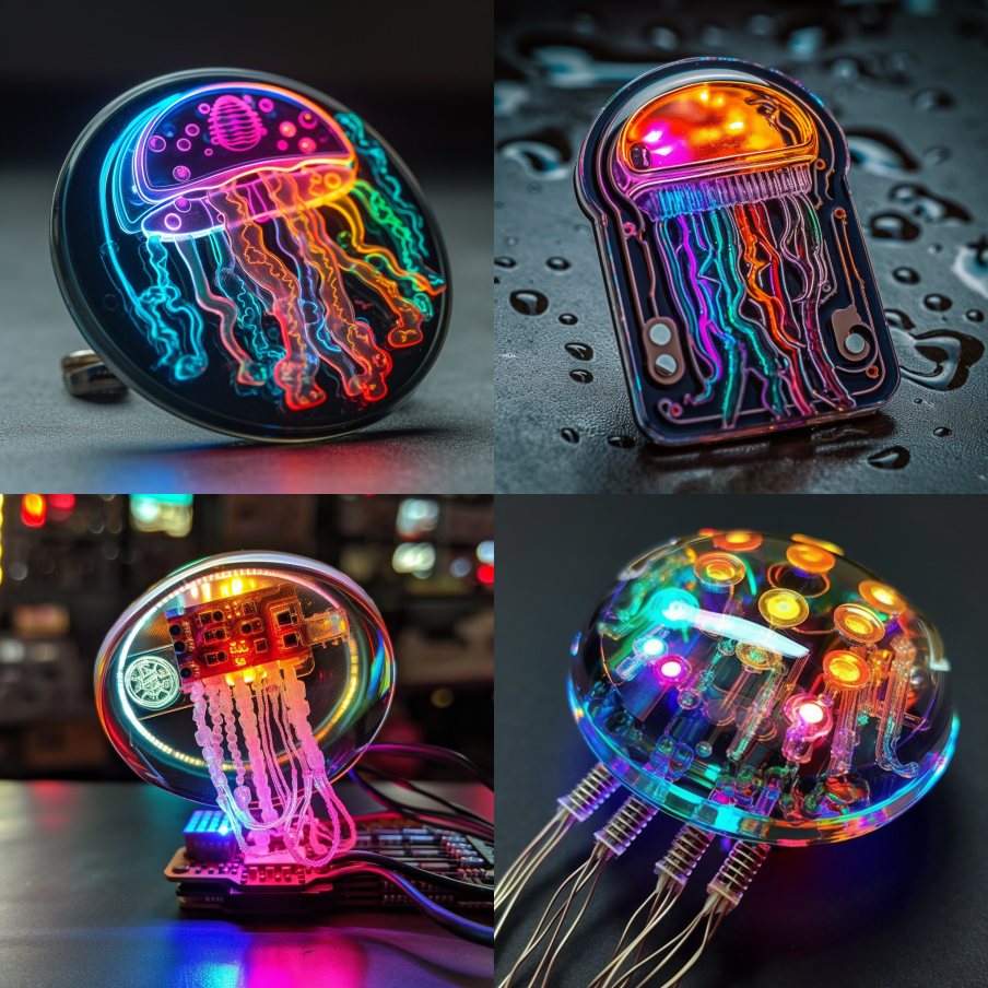
I won’t include all the sketches and ideas in this post but suffice to say: there were a lot of revisions.
While my sketch was used as the artwork for the board, Corvolu was super helpful in providing different art styles and digital art pointers. This helped us narrow down the style we wanted.
If you are doing your own project, you can definitely work with an outside artist instead of sketching it yourself. However, you’ll need to be able to define constraints (line sizes, art styles, etc) and may need to work through several iterations to accommodate technical constraints.
What do I mean by that? Let’s look at jellyfish tentacles as an example.
If we want realistic looking jellyfish tentacles in our design, we’ll need very thin lines that appear to be floating over a very large space. Here’s another AI output:
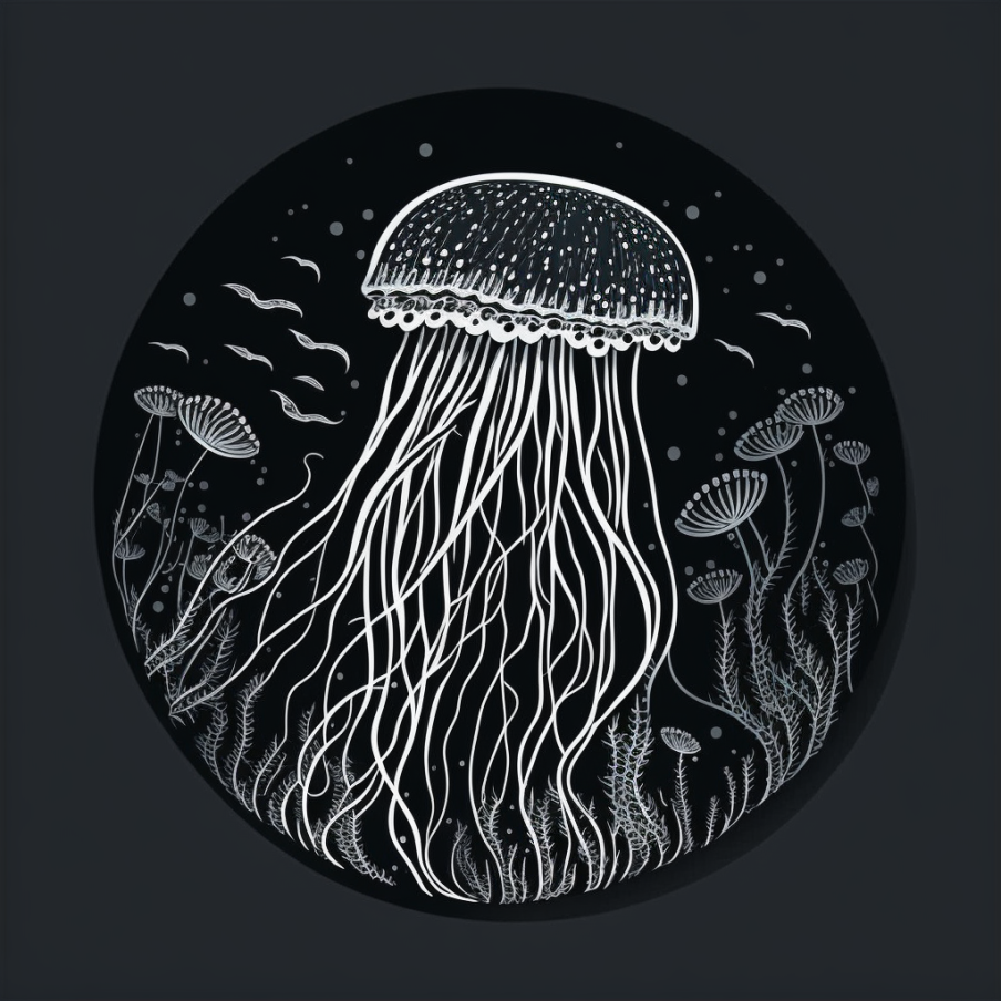
From a technical standpoint, we need LEDs to cover the entire area that needs to be lit. These LEDs will be situated around the edge of the jellyfish shape, shining inward (on the back of the board).
Here’s the final design marked up to show potential LED placement. I drew the design on an iPad using Procreate.
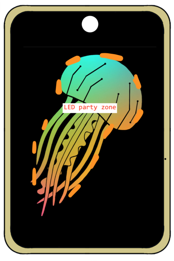
The more spread out the jellyfish is, the more LEDs we’ll need. And, as we covered earlier, more LEDs = more demand on our battery, more money, and more complexity. We can add diffusion to the back of the board with epoxy or hot glue, but diffusion can only do so much.
If we make the tentacles thicker and place them closer together, we can condense the area that needs lighting into one blob, limiting our LED needs. Here’s an early hand-drawn revision of mine with thicker areas, but they’re still pretty spread out:
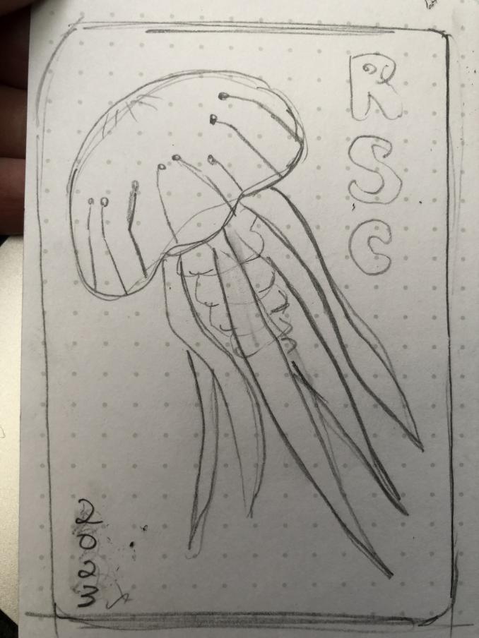
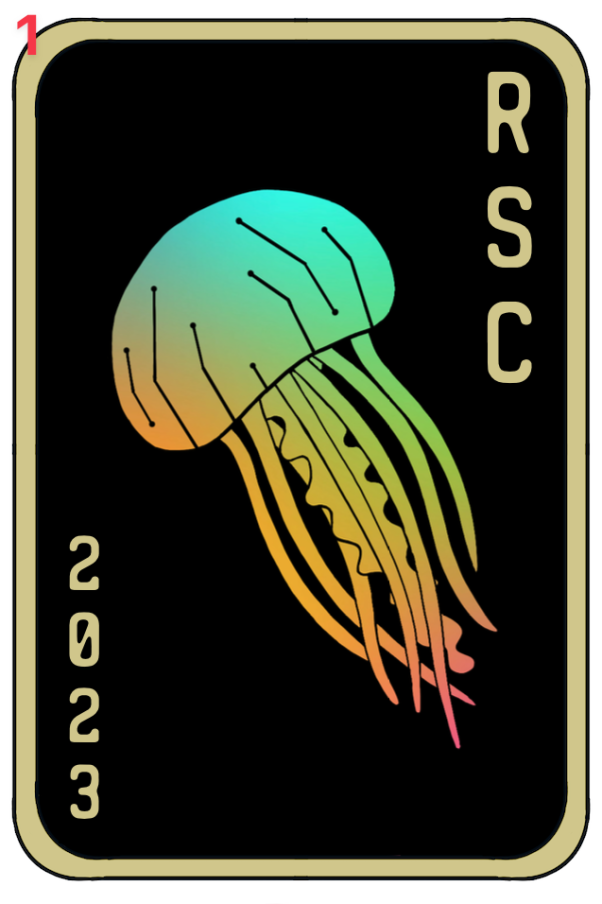
There were probably a dozen different iterations between the first and final drawings shown here, and many other sketches before that.
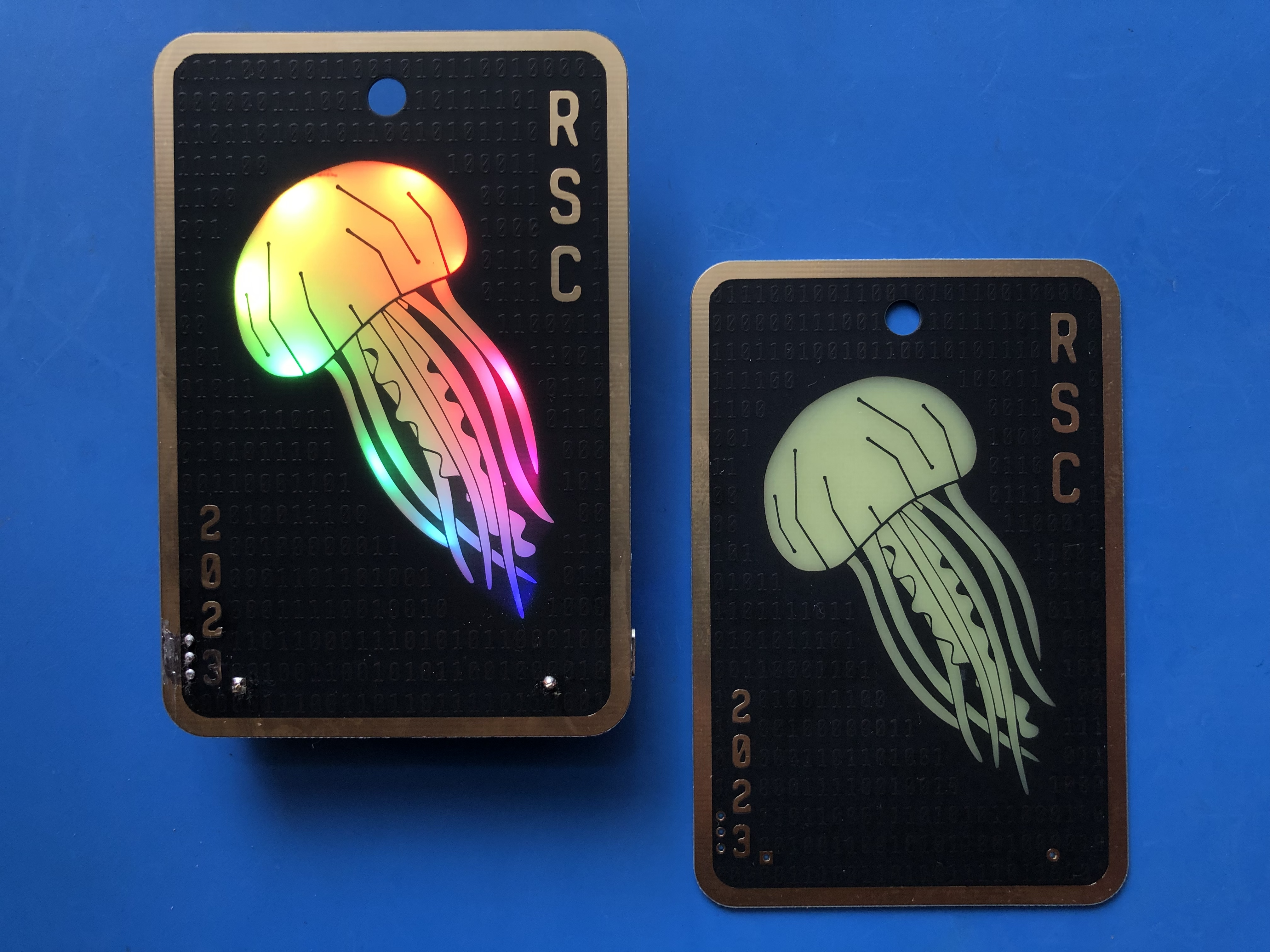
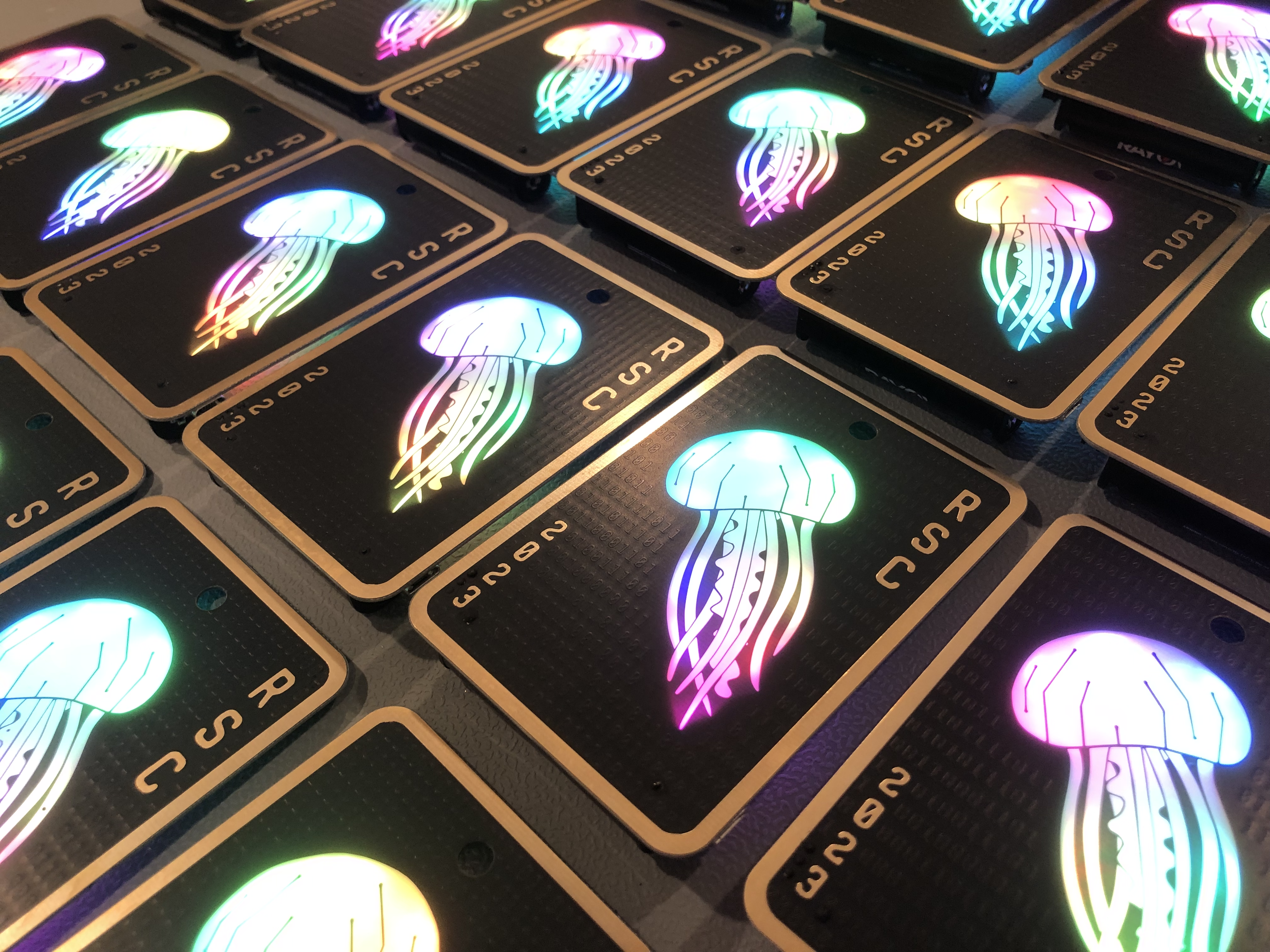
Each design is moving further away from a realistic jellyfish look, but it’s close enough that people still understand what it is. And we can light it up with a reasonable amount of LEDs. Here’s the final jellyfish design with the winning font choice.
Power management
I’ve already partially covered this–we expect to use a battery to power this board, which is why we’re so concerned about LED current demands.
We could alternatively have designed this as an SAO, which depending on who you ask is either a Simple Add-On or a Shitty Add-On that plugs into a bigger badge and is powered off of its batteries.
We could also have made this powered (only) off of a USB connection. But we wanted it to be wearable, so we’ll plan on coin cell batteries.
But as we’ll see, deciding on batteries is just the start of power management.
We also need to make sure that all of our parts are rated for the current demands we expect. And we’ll need to manage voltage and current for LEDs. Inconsistent voltage and current levels mean we either have weird flickering or our LEDs slowly get dimmer and dimmer over time.
We don’t want either of these, of course. We want bright jellyfish art the whole time!
Keeping It Simple
We’ve covered the problems, but we don’t really have a solution yet. Before I open up KiCad and start making a schematic, I want to get my circuit(s) successfully working on a breadboard. That means we need to shore up some of our circuit design ideas.
I was trying to keep this design as simple as possible so that it could get done on time. I am prone to scope creep and have to actively fight it!
But, alas, such simplicity was not meant to be. The original plan was to do LEDs in a static pattern, with a rainbow gradient. This would use single-color or possibly simple RGB LEDs with–and here’s the important part–no microcontroller.
Why? No microcontroller means no programming required. This means fewer parts, fewer supply chain issues, and also less setup with the boards (no need to flash the chip).
So where did my mind change?
I bought some LEDs, including 4 single color LEDs and 2 RGB LEDs. As you might recall from earlier in this very long blog post, I tested the LEDs brightness through a piece of FR4 that I had on hand.
The first problem: the LEDs did not shine brightly enough through the board. Okay, that’s simple enough: make the board thinner.
More LEDs, More Problems
But now, I was trying to figure out how to mix the colors in a gradient. Each LED color has a different brightness level, and your eye perceives different colors to be different brightnesses, despite having the same objective output.
Okay, we could PWM them, but that would require a microcontroller. Or we give up on the idea of having a totally smooth gradient.
But how would we make that gradient in the first place? We’d have to mix LED colors together with a limited set of colors, either single-color LEDs or RGB LEDs where there are three different colors in the same package.
We’ve got the same problem I have mentioned for the other LEDs: the forward voltages are all different.
What’s a forward voltage? It’s the voltage threshold above which the LED turns on. You can read more about it here. You can’t just put a higher voltage because LEDs are devices that have an exponential relationship between voltage and current, meaning a ton of current will go through the LED and maybe burn it out.
So let’s take a second and talk about how these puppies would get powered.
It’s Time to Talk About Boost Converters
Let’s assume we have a battery on the board. Let’s say for the sake of simplicity that it’s 3.3V, and all of our forward voltages are less than that (which isn’t actually the case, but we’ll ignore that for now).
We can use a resistor in series with the LED to limit the current through the LED. That’s cool, but what happens when the battery starts to drain? Our LED gets dimmer and dimmer until eventually the forward voltage constraint isn’t met. Then the LED party is over. Noooooo!
Instead, we can use a boost or buck converter, or a specialized constant current LED driver that will put out a constant 20mA at whatever voltage.
While the battery will eventually run out on any design, a driver or boost converter allows us to keep using battery power after the battery voltage has dipped below the LEDs’ forward voltage(s).
But remember: we said the voltage levels are different for different LEDs. This once again complicates our part selection. This is getting kind of annoying.
And all of this for static LEDs that might not even color balance how we want them to!
Maybe a Microcontroller Isn’t So Bad After All
At this point, I was both underwhelmed and overwhelmed with my choices at the same time. That’s quite a bit of complexity already, for a design I’m not thrilled about. I want a smooth rainbow gradient, and at the moment, that’s looking unlikely.
Instead, what if we use addressable RGB LEDs, like these ones from Adafruit? They have constant current drivers built in, eliminating that complexity mentioned earlier.
They require 5V, which means that we’ll need a boost converter if we use a coin cell battery or AA/AAA battery.
But: we will need a microcontroller. This is where the ATTiny85 comes in.
I’ve done a project like this before. Years ago, something came over me and I felt the need to add LEDs to high heels for a friend. The final product turned out awesome, if a bit impractical for most occasions. The LEDs cycled through a bunch of different colors, and had a cool effect with each step.
I thought, why reinvent the wheel?
At this point, some tech guilt set in. But I quickly got over it, realizing that I would find other wheels to needlessly reinvent in the future. It’s okay for me to take an easier route for this project, I decided. (Which was a good call, since I ran into plenty of other problems later in the process!)
The point of this prototyping step is to make sure that everything works as we think it will. So, I bought some ATTiny85s in a DIP package and made a breadboard circuit to show that I could program them (burn a bootloader, then a “blink the LED” program).
Then I added some of the addressable RGB LEDs to the circuit and controlled the colors with the ATTiny.
Behold, beautiful, software-controllable LED colors of my choosing!

Prototyping Everything Else
This blog post is already super long, so I’ll do my best to wrap things up.
At the start, I said you should prototype the main function of the design (LEDs + microcontroller, in our case) and then slowly evolve it to be more “badge-like”.
The breadboard photo above is powered off of an Arduino, which has a 5V voltage rail we can use.
Confident in my LED choice and software, I then ordered a boost converter that fit my electrical constraints. I also bought the accompanying parts I needed–an inductor and some capacitors. Some more expensive boot converters have these components included, but my choice did not. The values and sometimes even recommended part numbers and board layouts can be found in the component’s datasheet.
I soldered my power management circuit onto a prototype board (“solderable breadboard”). You can see there were a few different iterations.
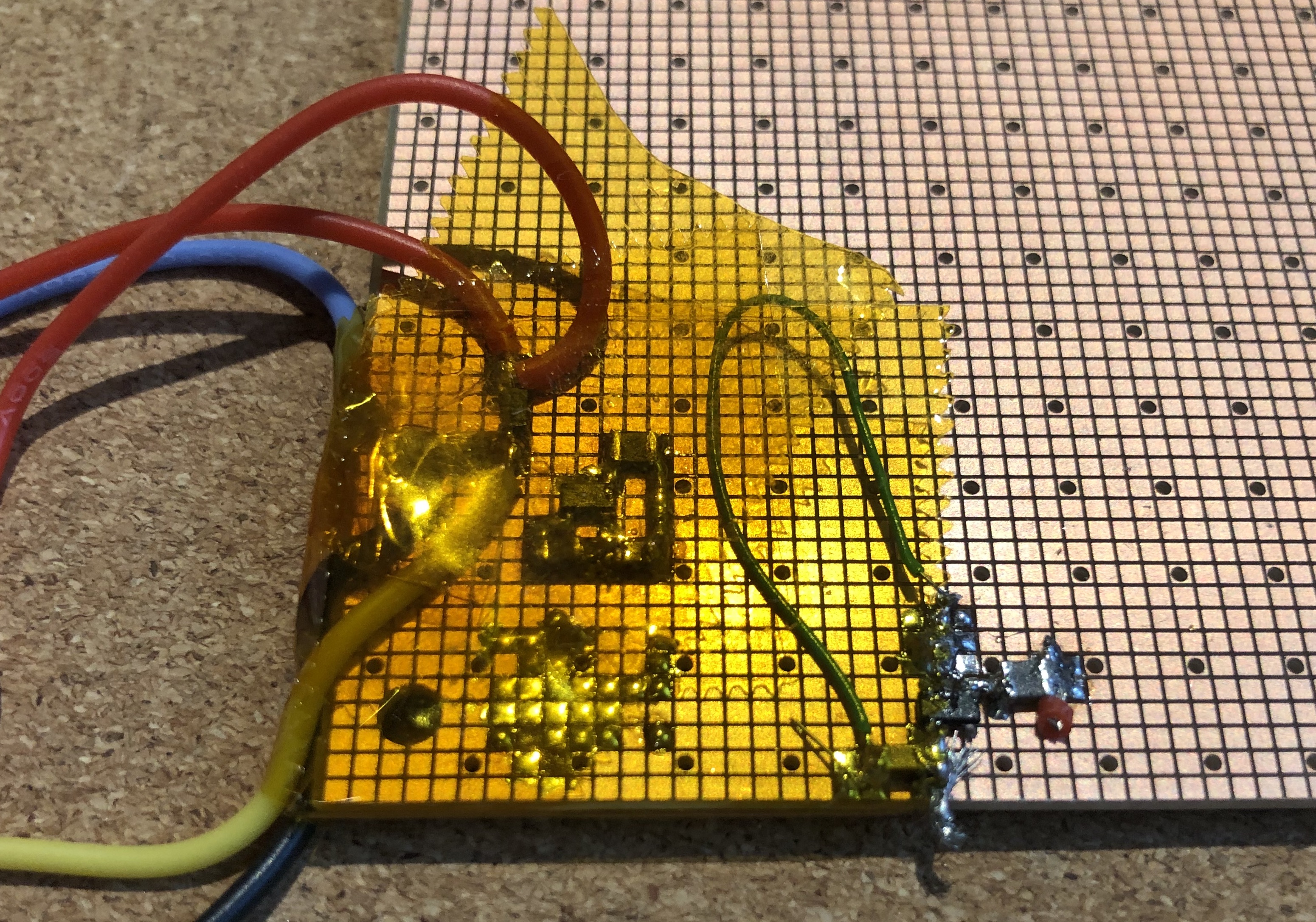
I also added some circuitry to protect against ESD and against the battery being put in backwards. I tested with some coin cells and quickly realized I’d be drawing too much current for the coin cells to keep up, so I switched to a AAA.
Note: I generally would not recommend addressable RGB LEDs for a badge, because they have very high power consumption. This is especially true when the board space limits you to one battery.
The reason I chose to use them anyway is because the rainbow gradient was so important to us. We also added a USB input for power, as many of the RSC members were interested in having the board plugged in at their desk.
The Universal Law of Complexity
They say that complexity can’t be created or destroyed, only moved elsewhere. So where are we moving the complexity in this design?
- Moving it to the parts manufacturers (built-in LED drivers) in exchange for money (higher cost per part) and slight increase in size.
- Moving color mixing complexity to parts manufacturer (addressable RGB LEDs) in exchange for money, and also into software in exchange for some of Jaime’s time and sanity.
- Avoid wireless features and difficult-to-find parts: let the rest of the world (and other parts of my current life) suffer from weird troubleshooting and supply chain complexity instead*.
- Added complexity due to needing to program things: make a header that makes it easier for us to program things (and also for end users to customize the jellyfish colors!), in exchange for board space and a slight increase in BOM cost and assembly time. We could also have the board house program things but what if I have a new color effect idea 2 days before Defcon?!
*Joke’s on me, I still ran into supply chain issues!
Do Not Pass Go (Yet)
We’ll get into KiCad in the next post, but I want to reiterate that I found components and breadboard the following things:
- Microcontroller selection
- Microcontroller programming method
- LED selection and color testing
- LED powering specifics
- Power management circuit
- UV LED: I haven’t mentioned it yet but we decided to add a blacklight LED on this board. This was tested as well.
Feeling confident (enough) to say that I had things figured out, I drew a circuit (on paper) to copy into KiCad. I can’t find the paper sketch or a photo of it, so you’ll have to take my word for it.
In the past, I’ve done a half-day workshop with circuit design (what we’ve talked about so far) and hands-on KiCad schematic and board layout exercises. If that sounds interesting or you know a conference that would appreciate it, please let me know! :)
Next up, we’ll turn this into a schematic and PCB layout in KiCad, and finally get some boards in hand!
